
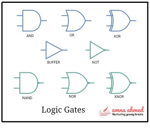
Logic Gates:
Logic Gates and Logic Circuits are the building blocks of digital circuits, perform simple logical operations on one or more outputs and produce a single output. With the help of connecting different logic gates, we can perform arithmetic and other logical operations within seconds.
- AND, OR, and NOT are basic logic gates
- Input and output are binary numbers
- The state of an input and output terminal often changes. That is it can change from 1 to 0 or vice versa. This is because the circuit processes the data and the state of the terminal changes accordingly
- There are many ways to implement logic gates like RTL (resistor transistor logic), DTL (diode transistor logic), TTL (transistor-transistor logic) and the most contemporary logic CMOS logic
Boolean Algebra:
The branch of algebra in which the variable values are true (binary 1) or false (binary 0).
We need to learn Boolean algebra because it simplifies the solution of logical problems. It also simplifies the design of logic circuits. According to the laws of Boolean algebra, there are seven logic gates which are stated below.
Whereas, NOT, AND and OR are three basic Boolean algebra operators. Boolean expressions use these operators and produce output that is either true or false.
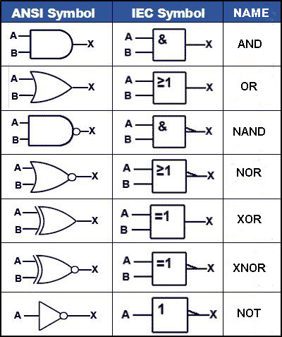
Logic Symbol:
A logic symbol is a graphical representation of elements in electronics. For each logic gate, there is a unique logic symbol. These symbols help to identify one component to another. For complex logic gates, we replace multiple gates with a single rectangular shape box. Inputs are on the left side while outputs are on the right. Some symbols are with bubbles and the rest of them are without bubbles. Some Boolean operators are inverse of each other. The bubble helps to identify them. For example, an AND gate has no bubble while its counterpart NAND has a bubble at the output side.
Logic Function Or Logic Expression Or Boolean Expression For Logic Gates
It is a mathematical depiction of a logic circuit. Provides the functionality of output in terms of input. The expression contains input and output variables along with Boolean operators ( . , + , ⊕). In the expressions below, Y is output, while A and B are two inputs. Some examples of Boolean expression for logic gates are given below:
Y = A.B
Y = A + B
Y = A ⊕ B
.Y = (A.B) ⊕ C
Logic expressions may contain more than one Boolean operator.
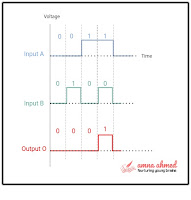
Logic Waveform Or Timing Diagram:
This is a graphical representation of the inputs and outputs of a logic circuit with respect to time. We can observe logic waveforms using an oscilloscope.
In the timing diagram, the x-axis shows the time while the y-axis represents the digital voltage levels. To analyze and examine digital systems, wave shapes are important. Some important wave parameters are discussed in this article. Figure below shows the AND gate timing diagram. You can easily understand the logic of examining this diagram. The output goes high only when both inputs are high.
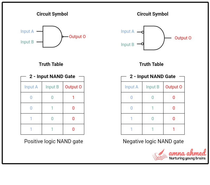
Polarity Indicator | Positive & Negative Logic:
The digital systems use both positive and negative logic depending upon the requirement. I have written on logic levels in my previous article. Positive logic means HIGH voltage represents binary 1 (ON state) while LOW voltage represents binary 0 (OFF state). Negative logic means LOW voltage represents binary 1 (ON state) while HIGH voltage represents binary 0 (OFF state). Figure below shows the positive and the negative logic of NAND gates. The bubbles or circles at the input side show the negative logic.
Truth Table:
A truth table curated all possible inputs and the corresponding output produced by a logic gate. All the logic gates can produce a single output (either 1 or 0).Each row contains possible input combinations and corresponding output produced by that combination. The logic expression or Boolean expression helps to evaluate the output of the logic system. With the help of a truth table, we can understand the operation of logic gates. To analyze the operation of any gate we need to go through its truth table. It is an invaluable tool in digital circuit design. For example, in the table below, the truth table of a 2 input AND gate is given. The number of inputs is two and possible input combinations are 4. Logic system with n-inputs, the truth table will have 2n possible input combinations. Input codes are always in ascending order.
| 2 Input AND Gate | ||
| Input A | Input B | Output |
| 0 | 0 | 0 |
| 1 | 0 | 0 |
| 0 | 1 | 0 |
| 1 | 1 | 1 |
Examples:
Evaluate the number of possible input combinations for a 4-input gate.
Number of inputs = n = 4
Number of possible input combinations = 2n = 24 = 16
Attempt Quiz:
Test your knowledge on logic gates and logic circuits. Attempt quiz here.