
The OR gate performs logical OR function. The output is high when any one input is high. The OR gate is widely used in digital circuits, alarm systems, and even microprocessor logic. In this post, we will explore the OR gate from different perspectives, including:
Learning Objectives:
- Multisim Live Simulation Results: Visualizing how an OR gate functions in a virtual circuit.
- Switches: Understanding the OR gate using mechanical switches.
- Diodes: Implementing an OR gate using diodes and resistors.
- BJT: Exploring how the OR gate implemented using bipolar transistors.
- OR gate IC
OR Gate Simulator
Select a gate, toggle the inputs, and watch the truth table light up.
Truth Table
Working:
Case 1:
- Input A = 0
- Input B = 0
- Output = 0
Case 2:
- Input A = 0
- Input B = 1
- Output = 1
Case 3:
- Input A = 1
- Input B = 0
- Output = 1
Case 4:
- Input A = 1
- Input B = 1
- Output = 1
In figure 1 the waveforms or timing diagram of OR gate are also given. The output pulse rises from 0 to 1 when any one of the two inputs are high.


Truth Table Of OR Gate:
| 2 Input OR Gate | ||
| Input A | Input B | Output |
| 0 | 0 | 0 |
| 1 | 0 | 1 |
| 0 | 1 | 1 |
| 1 | 1 | 1 |
Logical Expression Of OR Logic Gate:
Y = A + B
How is an OR gate made?
Logical OR Gate (Explain with the help of switches) | Switch Model and OR Logic:
Before starting the circuit model of OR gate, it is better to understand the concept of OR logic with the help of switches. The figure shows the switch model of OR gate. Two switch (switch A and switch B) are connected in parallel in between input and output. Input doesn’t reach when both switches are off (open). If anyone switches on (closed) input reaches to output.

Implementation Of OR Gate Using Diode Logic
Did you know you can build an OR gate using just diodes and a resistor? Practically diode circuit models are not used. But for beginners and better understanding of circuit analysis, implementation and designing, it is better to understand this topic. This is known as Diode Logic (DL) and is one of the simplest ways to implement basic logic functions.

Case 1:
See schematic in case 1, both inputs are connected to ground. Both diodes (D1 and D2) are off. Output is zero (LED remains off).
Case 2:
See schematic in case 2. Switch S1 is connected to a 5V source, turns on the D1 diode. Switch S2 is connected to the ground, D2 remains off. The current flows from 5V source to LED and the current grounded.
Case 3:
This case is the same as case 2.
Case 4:
See schematic in case 4. Both switches (S1 & S2) are connected to a 5V voltage source. As a result both the diodes are turned on. Current flows from 5V sources to the LED and grounded.
Implementation Of OR Logic Gate Using Transistor Logic:

Case 1:
Look at the schematic in case 1, both switches are open. There is no voltage at the base. Both transistors are turned off.
Case 2:
Look at the schematic in case 2, S1 is closed and hence Q1 is turned on. The transistor is in common collector configuration. Output is taken from the emitter. Once the transistor is ON, LED starts to glow.
Case 3:
Same as case 2.
Case 4:
Both transistors are ON. Current flows from emitter to collector and hence LED turns ON or output is logic high.
OR Gate IC – A Key Component in Digital Logic
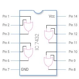
In actual digital circuits, an OR gate is never implemented with switches, diodes or BJT. In today’s circuits OR gates are used in the form of integrated circuits. IC 7432, which is a Quad 2-input OR Gate. IC 7432 is a digital logic IC that contains multiple OR gates in a single package. The most commonly used OR gate IC is the 7432, which belongs to the 74-series TTL logic family.
Frequently Asked Questions:
1. How to Use OR Gate IC in Circuits?
- Connect Pin 14 to +5V and Pin 7 to GND.
- Use input pairs (A, B) on any OR gate section and connect the output (Y) accordingly.
2. Discuss IC 7432 Specifications
- Contains Four (Quad) 2-input OR gates
- Operates at +5V (TTL logic)
- Comes in a 14-pin Dual In-line Package (DIP)
- Fast switching speed (~10ns propagation delay)
- Used in logic circuits, microcontrollers, and signal processing
3. How to Use OR Gate IC in Circuits?
It is ideal for logic controllers, combinational circuits, and digital switching applications. As you know, in a single IC of an OR gate (like 74HC32 Quad 2-Input OR Gate) there are 4 OR gates. Each gate has two inputs and a single output (obviously logic gates has only one output only). There are 14 pins in this IC. Pin 7 is Ground pin and pin 14 is Vcc. Connections are given below.
- Connect Pin 14 to +5V and Pin 7 to GND.
- Use input pairs (A, B) of any OR gate and connect the output (Y) accordingly.
4. What is the Boolean expression for an OR gate?
The Boolean expression for a two-input OR gate is:
Y=A+B
where ‘+‘ represents the logical OR operation.
5. How can you implement an OR gate using hardware components?
An OR gate can be implemented using:
- Diodes (Diode Logic OR Gate)
- Transistors (Transistor Logic OR Gate)
- Switches (Mechanical OR Gate)
- Integrated Circuits (IC 7432 – Quad 2-input OR Gates)
In this post, I discussed all the methods in details.
6. Can an OR gate have more than two inputs?
Yes, OR gates can have multiple inputs. Keep in mind that all logic gates can have more at least two inputs or more except the NOT gate, which has a single input and A single output. A 3-input OR gate works as follows:
Y=A+B+C
where the output is HIGH (1) if any of the inputs are HIGH.
7. What are the applications of OR gates?
Alarm and safety systems: The alarm activates if any sensor detects a problem.
Control and automation: A machine stops if any emergency switch or limit sensor is triggered.
Digital enable logic: Data or signals are allowed to pass when any one enable condition is active.
Interrupt and status circuits: A processor interrupt occurs if any interrupt line goes HIGH.
Arithmetic circuits: OR gates help in carry-generation and condition detection.
Register and memory control: Used to combine multiple write or set signals.
8. What is the difference between an OR gate and an XOR gate?
While an OR gate outputs 1 if at least one input is 1, an XOR (Exclusive-OR) gate outputs 1 only when inputs are different.
| Input A | Input B | OR Output | XOR Output |
|---|---|---|---|
| 0 | 0 | 0 | 0 |
| 0 | 1 | 1 | 1 |
| 1 | 0 | 1 | 1 |
| 1 | 1 | 1 | 0 |
9. Difference between logical OR and bitwise OR.
| Features | Logical OR (||) | Bitwise OR (|) |
|---|---|---|
| Type of Operation | Compares whole conditions | Compares values bit-by-bit |
| Works On | Boolean values (true/false) | Integer values (binary form) |
| Output | true or false | New integer after bitwise OR |
| Evaluation Method | Stops early if first is true | Evaluates all bits |
| Example | Input A =1 Input B = 0 Output= true | Input A= 1010 Input B = 1100 Output =1110 |
| Use cases | Decision-making in logic | Masking, flags, bit operations |