
Operational Amplifier Based Half Wave Rectifier:
Rectification is a process of converting an AC waveform into a single-direction pulsating DC. There is a filter block at the end of the rectification block. The purpose of this filter is to smooth the DC voltage (which is in the form of pulses).
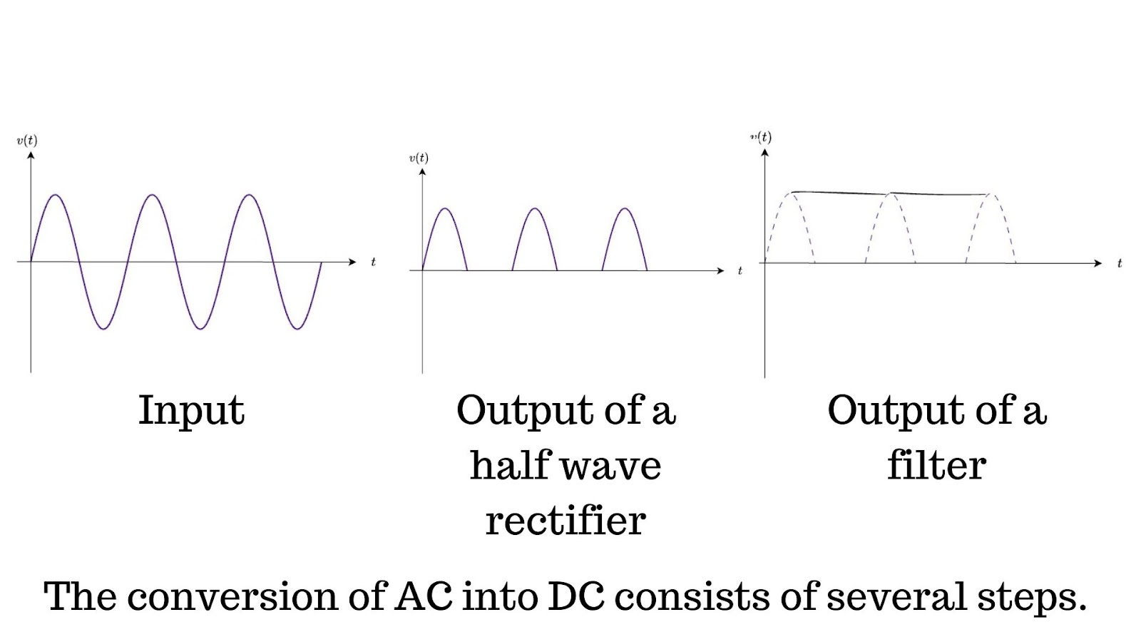 |
| The process of rectification |
Diode-based rectifier circuits are commonly employed in power supply designs. In these applications, the voltages being rectified have much greater values than the voltage drop of a diode. Passive rectifiers are suitable for large signals coming from transformer windings.
In some cases, like instrumentation applications, signals coming from sensors or transducers are of very small value in the order of millivolts. In these applications, it is impossible to employ diode rectifiers because of tiny signals (less than 0.7 V). So, here comes the concept of precision rectifiers.
What is an active rectifier?
There are many ways to implement active rectifiers. But I am going to discuss opamp-based precision rectifiers. I will discuss the half-wave precision rectifier in this post. Diodes along with Opamp form a special class of rectifiers known as precision rectifiers.
Precision Half Wave Rectifiers:
It consists of an Opamp and a diode in the feedback path. The input signal is at the Non-inverting terminal of the amplifier.
The circuit works as a voltage follower during the positive half cycle only.
vO = vi for vi >= 0
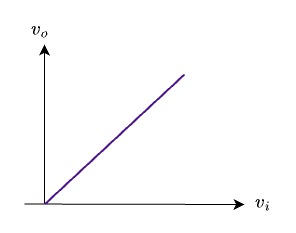
During the positive half cycle of the input signal, the output is also positive. The diode starts to conduct and a perfectly positive half cycle appears at the output. During the negative half cycle, the diode remains off.
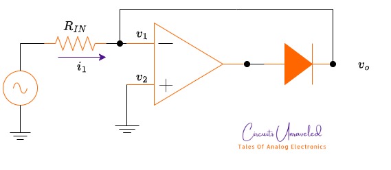 |
| OpAmp based half wave rectifier |
This circuit has some limitations. The biggest drawback of this circuit is the feedback loop. Have a look at the circuit. The feedback loop will open when the diode is off (in this case during the negative half cycle of the input signal, the diode turns off). Hence Opamp gets saturated. In each cycle of the input signal Opamp switches from the linear region and the saturation region.
Improved Circuit: Precision Half Wave Rectifier With Two Diodes:
To avoid the switching of Opamp from linear region to saturation region, again and again, this circuit is useful.
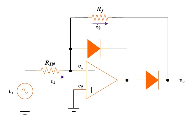 |
| The improved and faster circuit for half wave rectification. |
In this circuit, there are two diodes and two resistors along with the Opamp. The input signal is applied to the inverting terminal. In this circuit, there is negative feedback that never gets open and won’t let the Opamp to saturate. During the positive half cycle of the input signal, D2 is conducting. The output of the amplifier is negative (because of the inverting configuration), and the D2 is off during the positive half cycle.
During the negative half cycle, the D2 I’d off. The output of the Opamp is positive. The anode of the diode D1 is at the positive potential and starts to conduct and establish negative feedback through R2. The current flows through R2 is equal to the current flows through R1.
For R1 = R2, the transfer characteristics will be
vo = – vi for vi <= 0
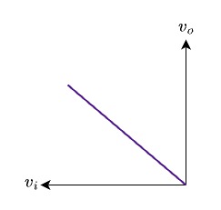 |
| The relationship between input and output of the given circuit. |
The prominent advantage of this circuit is that the feedback loop is closed throughout the circuit operation. D2 is included and hence the feedback loop remains closed.
Active Vs Passive Rectifiers: | Difference Between Active and Passive Rectification:
So, let’s discuss the difference between active and passive half-wave rectification. As a beginner, you might not be aware of the active rectification and passive rectification.
Passive rectifiers use simple silicon diodes to convert alternating current (AC) into direct current (DC). It is composed of a simple diode, followed by a load resistor.
 |
| A silicon diode is effectively converting AC to DC |
A diode is a unidirectional device that allows the flow of current only in one direction hence effectively converting AC into DC. For practical diodes, there is a forward voltage drop of 0.7V (for a silicon diode). They are suitable for rectification of large voltage signals.
What will happen if the input voltage is 1V, after rectification from a passive rectifier, the output voltage becomes 0.3V (there is a diode drop of 0.7V).
In this case, active rectifiers are used. They will effectively convert small AC voltages into DC voltages. They are composed of super diodes ( A super diode consists of an Opamp followed by a diode. The basic active rectifier consists of a super diode that is an operational amplifier and a diode. The negative feedback and high gain are responsible for bypassing the diode’s threshold voltage.
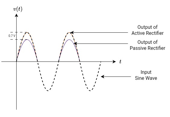 |
| Comparison between output of an active (precision) rectifiers Vs passive rectifiers |
Frequently Asked Questions:
1. What is a precision half wave rectifier?
A precision half wave rectifier is an op-amp based rectifier circuit that converts only one half of an AC signal into DC without the diode voltage drop error. It is especially useful for low voltage signals (like signals in milli volts or milli amperes )where ordinary rectifiers fail.
2. Why is it called a precision rectifier?
It is called a precision rectifier because the op-amp compensates for the diode’s forward voltage drop. This allows accurate rectification of signals even in the millivolt range.
3. How is a precision half wave rectifier different from a simple half wave rectifier?
A simple half wave rectifier uses only a diode and have a forward voltage drop (approximately 0.7 V for silicon diodes).
A precision half wave rectifier uses an op-amp and diode together, eliminating this error. It provides accurate rectification for small input signals.
4. Can a precision half wave rectifier work with very low input voltages?
Yes. This is one of its main advantages. It can accurately rectify signals as small as a few millivolts.
5. Which op-amp is commonly used in a precision half wave rectifier?
General-purpose op-amps like 741, LM358, or TL081 are commonly used. However, the choice depends on supply voltage, bandwidth, and input signal level.
6. Does the op-amp power supply affect the circuit operation?
Yes. The op-amp must be properly powered. If the input signal swings negative and the op-amp uses a single supply, the circuit may not work correctly. Dual supply operation is often preferred.
7. What happens during the negative half cycle of the input signal?
During the negative half cycle, the diode becomes reverse-biased, and the output remains nearly zero. Only the desired half cycle appears at the output.
8. Is the output of a precision half wave rectifier pure DC?
No. The output is a pulsating DC, similar to a simple half wave rectifier. Additional filtering circuits are required to obtain smooth DC.
9. What are the main applications of a precision half wave rectifier?
Precision half wave rectifiers are commonly used in:
Low-level sensor signal processing
Signal conditioning circuits
AC voltmeters
Peak detectors
Instrumentation systems
- Low-level sensor signal processing
10. Can a precision half wave rectifier handle high-frequency signals?
Its performance depends on the op-amp’s slew rate and bandwidth. At high frequencies, distortion may occur if the op-amp cannot respond fast enough.
11. Why is a diode still used if the op-amp removes voltage drop?
The diode controls the direction of current flow and enables selective rectification. The op-amp simply compensates for the diode’s voltage drop.
12. What are the limitations of a precision half wave rectifier?
Some limitations include:
- Increased circuit complexity
- Dependence on op-amp characteristics
- Limited high-frequency performance
- Requires proper power supply configuration
13. Is a precision half wave rectifier better than a precision full wave rectifier?
It depends on the application. A precision half wave rectifier is simpler, while a precision full wave rectifier provides better efficiency and smoother output.
14. Can this circuit be simulated before implementation?
Yes. Precision half wave rectifiers can be easily simulated using tools like SPICE-based simulators to verify performance before hardware implementation.
15. Is this topic important for exams and interviews?
Yes. Precision rectifiers are frequently asked in analog electronics exams, viva questions, and basic electronics interviews, especially for op-amp applications.
My recommendation for the best opamps.
To achieve high accuracy in your waveforms, I recommend using the following high input impedance and low noise for signal clarity.
Precision Op-Amp UA741CP IC OPAMP from Texas Instruments
Recommended Books
I always read these books, while preparing these blog posts.
Electronic devices by Thomas L Floyd
Microelectronic Circuits (The Oxford Series in Electrical and Computer Engineering) 8th Edition